-
- Contact Us
90T03P MOSFET: Complete Specs, Pinout & Ratings Digest
The 90T03P is rated for up to 75 A continuous current and a 30 V drain–source rating with RDS(on) as low as ~4 mΩ — specs that make it a common choice in medium‑power DC–DC and motor‑drive designs. This digest consolidates verified headline specs, a confirmed pinout summary, thermal and switching considerations, common equivalents, sourcing cautions, and a hands‑on checklist so power‑electronics engineers, experienced hobbyists, and procurement specialists can verify, test, and apply the device confidently. The goal is a concise, data‑driven reference that supports bench verification and design sizing; the article length and sectioning are sized to give a focused introduction, data deep dive, practical verification steps, cross‑reference options, and an actionable design checklist for typical 12 V/30 A designs.
1 — 90T03P MOSFET: Overview & Key Specs (Background introduction)

1.1 — Quick spec snapshot (BVDSS, ID, RDS(on), VGS(th), package)
| Parameter | Typical / Test Condition | Value (typ / abs) |
|---|---|---|
| BVDSS (Drain‑Source Voltage) | Absolute maximum | 30 V (abs) |
| Continuous Drain Current (ID) | PCB, TA dependent | 75 A (typ / package dependent) |
| RDS(on) | VGS = 10 V (typ) | ≈ 4 mΩ (typ); check datasheet for VGS = 4.5 V |
| VGS(th) (threshold) | ID = 250 µA | Typical: a few volts (consult datasheet) |
| Max VGS | Absolute | ±20 V (typ for similar devices) |
| Package | Common variants | TO‑220, TO‑252 (DPAK) — see recommended operating ranges |
Notes: the table highlights headline values and flags which numbers are absolute maximums versus typical/test conditions. Always confirm test conditions (VGS test voltage, case/ambient temperatures) on the actual datasheet when finalizing thermal calculations or selecting gate drive voltages.
1.2 — Package types & pinout summary (TO‑220 / TO‑252 variants)
Standard mechanical formats for this family include through‑hole TO‑220 and surface‑mount TO‑252 (DPAK). Pin assignment normally follows the convention Gate / Drain / Source from left to right when viewing the front of the package for TO‑220; for DPAK, the tab is typically the Drain. For clarity, include a labelled image with alt text "90T03P pinout diagram" next to the footprint on your design page. Practical advice: mark the tab/drain on the PCB, add thermal vias under the pad for DPAK, and keep gate traces short and low inductance. The word pinout should appear on the assembly drawing and in the BOM notes so technicians and test engineers can cross‑check orientation during placement.
1.3 — Typical applications and why designers pick 90T03P
Common applications include synchronous buck power stages, BLDC motor drivers, high‑current load switches, and DC‑DC converters where low conduction loss is essential at moderate bus voltages (up to 30 V). Designers favor the device for the low RDS(on) that reduces I²R conduction losses, but must balance that against the low VDS rating — a 30 V ceiling limits use on higher‑voltage rails and requires robust transient suppression. The practical tradeoff is clear: excellent efficiency for low‑voltage, high‑current switching, with care required for SOA and avalanche energy in inductive circuits.
2 — Deep Dive: Electrical Characteristics & Performance Data (Data analysis)
2.1 — DC characteristics: RDS(on) behavior, ID vs VDS curves, VGS dependence
RDS(on) is strongly dependent on VGS and temperature: for this category, RDS(on) measured at VGS = 10 V gives the lowest typical value (~4 mΩ). At reduced gate drive (e.g., VGS = 4.5 V) expect higher RDS(on) and therefore larger conduction losses; datasheet curves typically show RDS(on) rising roughly linearly with junction temperature. ID vs VDS (output) curves reveal the linear and saturation regions and help determine safe operating currents at given VDS; consult the datasheet's transfer and output characteristics when sizing margins. Best practice: use the RDS(on) specified at the expected VGS and apply temperature derating (RDS(on) increases with Tj, often by 0.3–0.5%/°C depending on technology) when predicting losses across the operating range.
2.2 — Switching characteristics & dynamic parameters (Qg, td(on), tr, tf)
Key dynamic parameters include total gate charge (Qg), Miller charge (Qgd), turn‑on delay (td(on)), rise/fall times (tr, tf), and reverse transfer capacitance. Qg determines gate drive energy (Eg = 0.5 * Qg * VGS²) and thus gate driver current requirements; Qgd correlates with the Miller plateau and impacts dv/dt behavior. For design estimation use datasheet Qg at VGS = 10 V; devices in this class commonly have Qg in the tens of nanocoulombs range. Switching loss per cycle can be approximated as Esw ≈ 0.5 * VDS * ID * (tr + tf); multiply by switching frequency to get Psw. Use these formulas with the device's measured tr/tf to predict switching loss and select an appropriate gate driver and snubber strategy.
2.3 — Thermal & absolute maximum ratings (RthJA/RthJC, SOA, junction temp)
Thermal resistance metrics (RthJC, RthJA) and the maximum junction temperature are critical for reliability. RthJC (junction‑to‑case) is low on tabbed packages and useful when a heatsink is attached; RthJA (junction‑to‑ambient) on a PCB depends heavily on copper area and thermal vias. Use P = I² * RDS(on) + Psw to compute total dissipation; then ΔTj = P * RthJA to estimate junction rise. The Safe Operating Area (SOA) graph shows allowable VDS/ID combinations over time; for inductive switching ensure avalanche energy and transient handling are within limits. If ΔTj approaches the margin to Tj(max), plan for heat sinking, larger copper, or paralleling devices with careful gate balancing.
3 — How to Verify Pinout, Test & Read the Datasheet (Method/guide)
3.1 — Pinout verification: physical checks and continuity tests
Step‑by‑step verification: 1) Visually confirm package marking and orientation against the mechanical drawing; 2) Use a DMM continuity/diode mode to identify body diode between Drain and Source (diode conducts from Source to Drain in diode test when forward biased); 3) Check Gate‑to‑Source insulation (expect open/very high resistance) and Gate‑to‑Drain leakage characteristics; 4) Confirm tab continuity to Drain on tabbed packages. Record results and label parts before soldering. Vendor pin numbering can vary between suppliers; always cross‑check part marking and the vendor's mechanical drawing to avoid mis‑wiring the pinout on the PCB.
3.2 — Practical bench tests to confirm RDS(on) and switching behavior
Safe RDS(on) check: set up a low‑voltage (e.g., 5–12 V) supply, current‑limited to the intended test current (a few amps for initial check), apply a known VGS (use 10 V gate drive for the device’s low‑RDS condition), and measure VDS to compute RDS(on) = VDS/ID. For switching: use a half‑bridge or clamp circuit with proper gate resistor, capture turn‑on/turn‑off waveforms with a scope and high‑bandwidth probe, and observe Miller plateau and dv/dt. Recommended instruments: bench PSU with current limit, 100 MHz+ oscilloscope with 10:1 probes or isolated amplifiers for high side, a pulse generator or gate driver, and a current probe. Follow safety practices for capacitive/inductive loads and use series resistance to limit energy during initial tests.
3.3 — PCB footprint, thermal mounting & layout best practices
Layout checklist: place the gate drive as close as possible to the gate pin and use a low‑inductance return path; keep drain copper pour large and directly tied to the tab or pad; stitch thermal vias under DPAK drain pads to inner‑layer copper. For TO‑220, use an insulating pad and torque‑specified screw or a recommended heatsink mount; for DPAK, use multiple vias and a thermal slug area with solder paste pattern optimized for reflow. Add a Kelvin sense if precision RDS(on) measurement or current sharing is required. Gate resistor placement should be near the gate pad; include a footprint for a small RC snubber or TVS on the drain to protect against transients and to shape dv/dt if required by the gate drive or driven switching MOSFETs.
4 — Equivalents, Cross‑References & Sourcing (Case studies / examples)
4.1 — Common equivalents and pin‑compatible alternatives
Equivalent parts can simplify sourcing. Common cross‑references include vendor variants like AP90T03P and packages with HF (halogen‑free) suffixes. When substituting, compare RDS(on) at the intended VGS, thermal ratings, and package lead‑frame details; slight differences in die size or thermal resistance materially affect steady‑state temperature and SOA. Also check VGS(max), Qg, and avalanche energy ratings — matching just the RDS(on) is not sufficient for robust replacements.
4.2 — Bench comparison: 90T03P vs comparable 30 V MOSFETs
Suggested test matrix: measure RDS(on) at VGS = 10 V and 4.5 V across a temperature sweep (25–125 °C), capture Qg and Qgd at the standard gate voltages, and run switching loss tests in a half‑bridge at the target frequency and load current. Plot RDS(on) vs temperature and Psw vs frequency to highlight differences. Expect the low‑RDS devices to show clearly lower conduction loss but potentially larger gate charge; the net efficiency depends on switching frequency and duty cycle.
4.3 — Sourcing, counterfeit risk, and distributor notes
Buy from authorized distributors or reputable franchised sellers; check packaging, date codes, and marking against manufacturer mechanical drawings. Red flags include inconsistent marking fonts, missing lot codes, unlabeled reels, or suspiciously low unit pricing for small quantities. Request the latest revision of the datasheet and compare the vendor part marking to the published drawing. For higher‑volume buys, ask for traceability and certificates of conformance to reduce counterfeit risk.
5 — Design & Ratings Checklist: Sizing, Derating & Example Calculations (Actionable guidance)
5.1 — Sizing example: calculate losses and temp rise for a 12 V / 30 A buck stage
Conduction loss: Pcond = I² * RDS(on) = 30² * 0.004 = 3.6 W. Switching loss estimate: with VDS ≈ 12 V, ID = 30 A, and combined rise+fall ~30 ns at fs = 200 kHz, Esw ≈ 0.5 * 12 * 30 * 30e‑9 = 5.4 µJ per cycle; Psw = 5.4 µJ * 200 kHz ≈ 1.08 W. Total Pdiss ≈ 4.68 W. If board RthJA ~ 40 °C/W (conservative DPAK on small copper area), ΔTj ≈ 4.68 * 40 ≈ 187 °C — unacceptable without heatsinking or larger copper. Action: increase copper area, add thermal vias, reduce switching freq or parallel MOSFETs, or move to a heatsinked TO‑220 with lower RthJA to bring ΔTj into acceptable margins.
5.2 — Pinout wiring checklist and recommended gate drive parameters
Checklist: 1) Short gate trace from driver to gate pad; 2) Route gate return close to driver ground; 3) Place gate resistor (5–10 Ω) at the gate pad to damp ringing; 4) Use a 10–100 nF gate‑to‑source clamp (if needed) and a small RC snubber on the drain for aggressive transition shaping. Recommended VGS is 10 V for lowest RDS(on); if using logic‑level drive at 5 V, validate the RDS(on) at VGS = 4.5–5 V on the datasheet. Provide a gate driver capable of sourcing/sinking the peak gate current = Qg * (switching frequency) per transition and ensure the layout supports the required di/dt without coupling noise into sensitive control nodes.
5.3 — Final spec table & recommended part numbers for different use cases
| Use Case | Recommendation |
|---|---|
| High‑efficiency switching buck | Low RDS(on) TO‑252 / TO‑220 variants (AP90T03P family) |
| Surface‑mount, thermally enhanced | DPAK variant with thermal vias and copper slug |
| Prototype hand‑solder / heatsink mount | TO‑220 variant for easy heatsinking |
Note: verify exact part numbers and suffixes (HF, temperature grade) against the vendor datasheet for revision and packaging options before procurement.
Summary
- 90T03P delivers low conduction loss at moderate voltages (30 V, ~4 mΩ, 75 A class), making it well suited to 12 V/30 A buck stages provided the SOA and thermal strategy are respected.
- Verify the pinout physically (visual, diode/continuity checks) and perform low‑voltage RDS(on) tests and switching captures on the bench before committing to production.
- Design checklist: use short gate traces, gate resistor (5–10 Ω), ample drain copper and thermal vias, and compute conduction + switching losses to select heatsinking or paralleling.
- Sourcing tip: prefer authorized distributors, confirm part marking and datasheet revision, and be cautious of anomalous pricing or packaging as counterfeit indicators.
Frequently Asked Questions
What is the best way to test 90T03P MOSFET RDS(on) on the bench?
Use a low‑voltage, current‑limited setup: clamp VGS at the datasheet test voltage (10 V for best‑case RDS(on)), drive a controlled current (several amps for initial check), and measure VDS with the DMM to compute RDS(on) = VDS/ID. Keep the device cool between tests and use short Kelvin leads for precise measurement. For more accurate temperature‑dependent characterization, repeat at elevated case temperature or place the device on a temperature‑controlled fixture and log RDS(on) vs Tj.
How should I read the 90T03P pinout to avoid assembly errors?
Always cross‑reference the package mechanical drawing in the datasheet to confirm pin numbering and tab connections. For TO‑220, Gate / Drain / Source is typically left to right on the front face; the tab is usually Drain. For DPAK, the tab is the Drain and pin assignment follows the vendor drawing. Perform a quick continuity/diode test before soldering to confirm the body diode orientation and tab‑to‑drain connection; document the confirmed pinout on the PCB assembly drawing.
Which gate drive voltage is recommended for optimal efficiency with this MOSFET?
Drive the gate to 10 V for lowest RDS(on) and best conduction efficiency; many devices in this class are specified at VGS = 10 V. If using 5 V logic‑level drivers, verify the specified RDS(on) at VGS = 4.5–5 V on the datasheet and confirm thermal margin calculations, since RDS(on) typically increases significantly at lower gate voltages. Ensure the gate driver can source/sink the required gate charge quickly to limit transition losses and ringing.
- Technical Features of PMIC DC-DC Switching Regulator TPS54202DDCR
- STM32F030K6T6: A High-Performance Core Component for Embedded Systems
- Tamura L34S1T2D15 Datasheet Breakdown: Key Specs & Limits
- PAL6055.700HLT Datasheet: Complete Technical Report
- FDP027N08B MOSFET Datasheet Deep-Dive: Key Specs & Test Data
- LT1074IT7: Complete Specs & Key Parameters Breakdown
- How to Verify G88MP061028 Datasheet and Specs - Checklist
- NFAQ0860L36T Datasheet: Measured IPM Performance Report
- 90T03P MOSFET: Complete Specs, Pinout & Ratings Digest
- 3386F-1-101LF Datasheet & Specs — Pinout, Ratings, Sources
-
 MM74HC4050NSanyo Semiconductor/onsemiIC BUFFER NON-INVERT 6V 16DIP
 -
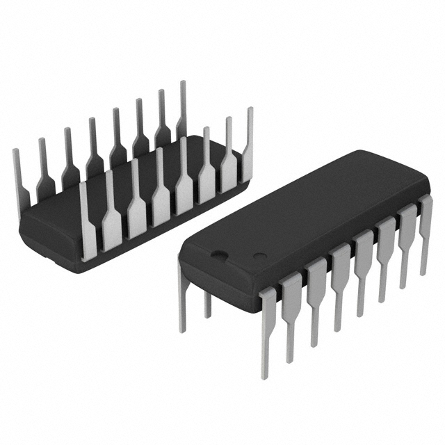 MM74HC4049NSanyo Semiconductor/onsemiIC BUFFER NON-INVERT 6V 16DIP
 -
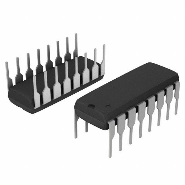 MM74HC4040NSanyo Semiconductor/onsemiIC BINARY COUNTER 12-BIT 16DIP
 -
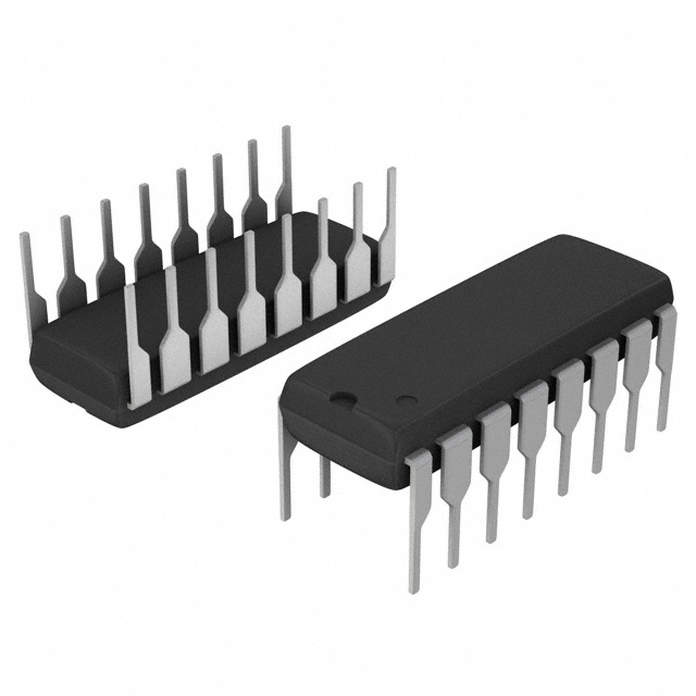 MM74HC4020NSanyo Semiconductor/onsemiIC BINARY COUNTER 14-BIT 16DIP
 -
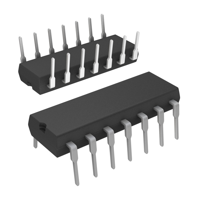 MM74HC393NSanyo Semiconductor/onsemiIC BINARY COUNTR DL 4BIT 14MDIP
 -
 MM74HC374NSanyo Semiconductor/onsemiIC FF D-TYPE SNGL 8BIT 20DIP
 -
 MM74HC373NSanyo Semiconductor/onsemiIC D-TYPE TRANSP SGL 8:8 20DIP
 -
 LT1213CS8Linear Technology (Analog Devices, Inc.)IC OPAMP GP 2 CIRCUIT 8SO
 -
 MM74HC259NSanyo Semiconductor/onsemiIC LATCH ADDRESS 8BIT 16-DIP
 -
 MM74HC251NSanyo Semiconductor/onsemiIC MULTIPLEXER 1 X 8:1 16DIP

