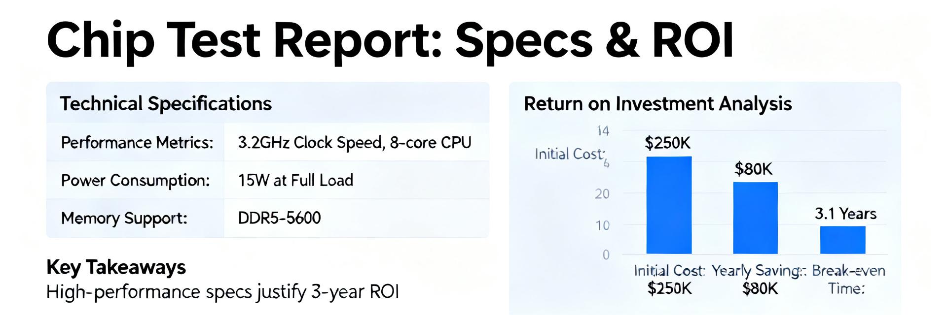
PE-65612NL: Specs & Key Metrics for Audio Isolation
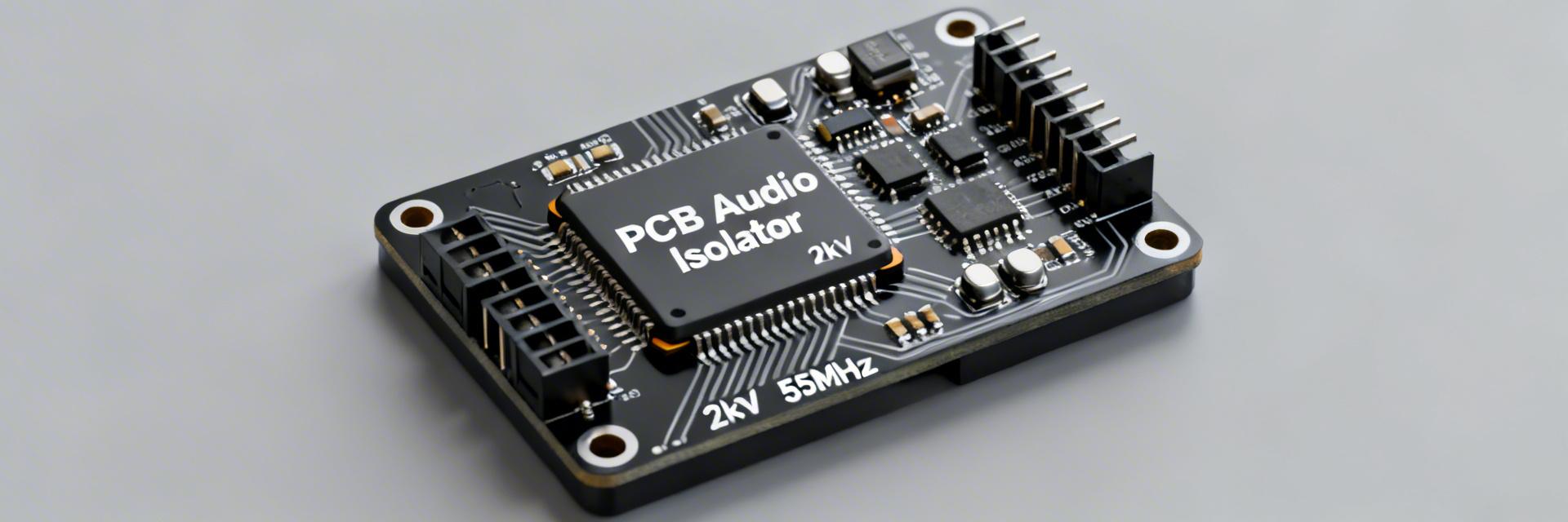
The PE-65612NL is specified for 2 kVrms isolation, a 100 kHz–55 MHz usable frequency window, and a compact 0.500" × 0.350" footprint, positioning it for high-speed isolated digital audio links.
Safety margin, signal-bandwidth headroom, and minimal PCB area are informed by these metrics, ensuring integrity in high-performance environments.
Technical Performance Visualization
Choosing a component with both high isolation and wide bandwidth reduces the need for additional signal conditioning.
Background: Why Audio Isolation Matters
Part Summary & Physical Footprint
The PE-65612NL is a single-channel, four-terminal PCB-mounted transformer-like isolator in a low-profile package. With mechanical dimensions of roughly 0.500" × 0.350" and a seated height of approximately 0.250", it weighs just 1.2 g. These attributes make it ideal for high-density, automated pick-and-place assembly.
Role of Isolation in Digital Audio Systems
Isolation protects circuits and maintains data integrity across system boundaries. By breaking ground loops and providing galvanic separation, the device limits common-mode disturbances. The 2 kVrms rating ensures grounds remain separated while passing high-rate serialized audio without bit errors.
Key Specs & Electrical Metrics
| Metric Category | Specification Detail | Engineering Implication |
|---|---|---|
| Isolation Voltage | 2 kVrms | High safety margin; requires Hipot validation. |
| Frequency Bandwidth | 100 kHz – 55 MHz | Supports PCM, AES3, and high-rate serialized audio. |
| Turns Ratio | 0.6 : 1 | ~ -4 dB level reduction; requires gain compensation. |
| Operating Temperature | 0°C to 70°C (Standard) | Commercial grade; requires derating for extreme environments. |
Frequency & Signal Integrity
- •Insertion Loss: Typically modest; measure S21 across the protocol band.
- •Phase Jitter: Maintain low group delay variation to avoid bit timing errors.
- •CMRR: High winding symmetry provides critical common-mode rejection.
PCB Design Guide
- •Creepage: Maintain clear separation between primary and secondary copper.
- •Keep-out Zones: Use board slots or cuts to prevent conductive bridging.
- •Grounding: Route return paths to their respective sides; do not cross the split.
Testing, Validation & Selection Checklist
Lab Test Protocol
- Hipot/Isolation (Safety First)
- S-parameter sweeps (S21/S11)
- Insertion loss and phase check
- Common-mode rejection (CMR)
- Thermal cycling stress
Procurement Verification
- Confirm 2 kVrms rating
- Verify 100kHz-55MHz band
- Validate 0.6 turns ratio
- Check footprint tolerances
- Request lot traceability