XG4C-4031 datasheet: pinout, MIL specs & test data
Key Takeaways
- MIL-Spec Reliability: Full MIL-C-83503 compliance for mission-critical aerospace and industrial use.
- Extreme Versatility: 40-position, 2.54mm pitch supports high-density logic and signal routing.
- Thermal Resilience: Operational from -55°C to +125°C, ensuring stability in harsh environments.
- Superior Insulation: >1 GΩ resistance prevents signal leakage in sensitive analog/digital circuits.
The XG4C-4031 is a 40-position, 2.54 mm (0.100") pitch rectangular MIL connector with typical ratings such as 1 A contact current, 250 VAC dielectric rating, >1 GΩ insulation resistance and operating range down to -55 °C. This article delivers a clear pinout, a MIL-C-83503 compliance summary, and guidance to interpret and verify datasheet and test data for design and test engineers using the XG4C-4031 datasheet.
Readers will get a concise spec table, pin numbering and PCB footprint guidance, MIL-C-83503 mapping, test templates for electrical and mechanical checks, and a practical pre-production checklist to validate parts before first production. Emphasis is on actionable measurement setups, pass/fail thresholds, and sample-size recommendations for early validation and DFM review.
Product Overview & Key Specifications
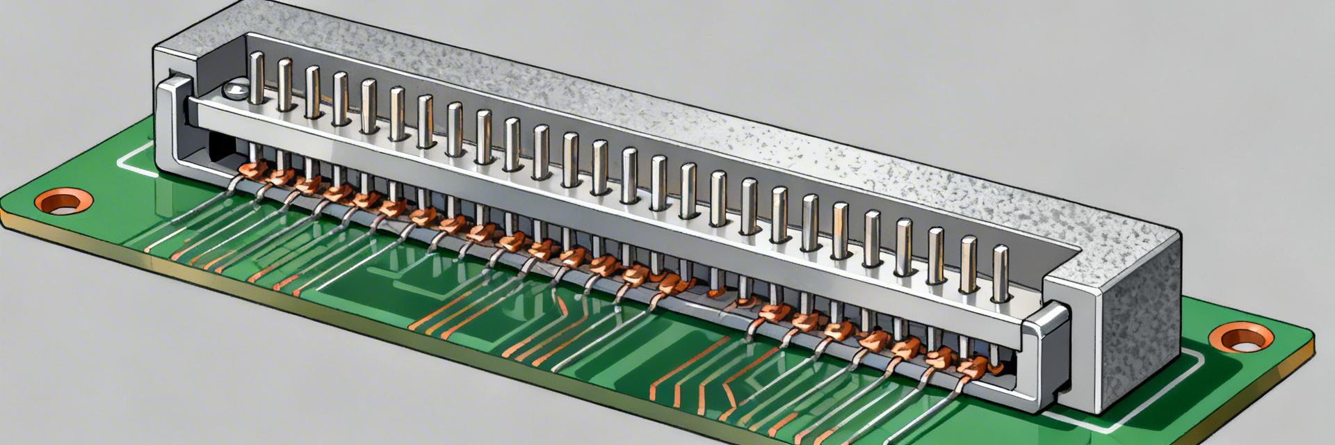
Quick Spec Summary
| Parameter | Value / Notes |
|---|---|
| Positions | 40 |
| Pitch | 2.54 mm (0.100") |
| Rated current | 1 A (contact dependent) |
| Rated voltage | 250 VAC dielectric |
| Contact resistance | <20 mΩ typical (variant dependent) |
| Insulation resistance | >1 GΩ typical |
| Operating temp | -55 °C to +125 °C (variant tolerance) |
| Mating style / Mount | Straight plug / PCB mount |
Comparative Analysis: XG4C-4031 vs. Standard Connectors
| Feature | XG4C-4031 (MIL-Spec) | Standard Commercial 2.54mm |
|---|---|---|
| Temp. Range | -55°C to +125°C | -25°C to +85°C |
| Durability | MIL-C-83503 Certified | Vendor Specific |
| Insulation | >1,000 MΩ | ~500 MΩ |
| Housing Material | PBT (UL94V-0) | Standard Nylon/ABS |
Form Factor, Locking & Mechanical Features
The connector body is a rectangular, low-profile housing with keyed polarizing features to prevent 180° mis-mates; many variants include latch or snap locks and optional backing rails. Recommended mechanical drawings to include in the documentation pack are front view (pin map), side view (stack height), top view (pitch and row spacing), exploded view, and cross-section showing plating and contact engagement.
Pinout Details and PCB Footprint Guidance
Pin Numbering & Signal Mapping
Pin numbering convention: rows A/B (or row 1/2) left-to-right yields pins 0–39 across two rows (0–19 on row 1, 20–39 on row 2) or numbered 1–40 depending on house style. Below is an example mapping for a standard digital interface:
| Pin | Signal | Net Purpose | Test Point |
|---|---|---|---|
| 1 | VCC_3V3 | Power | TP1 |
| 2 | GND | Return | TP2 |
| 3 | SDA | I2C Data | TP3 |
| 4 | SCL | I2C Clock | TP4 |
"When designing with the XG4C-4031, avoid the common mistake of undersizing your thermal relief on ground pins. For MIL-spec environments, we recommend a minimum trace width of 15 mils for the 1A power paths. Also, ensure your pick-and-place files reference the geometric center of the 40-pin body rather than Pin 1 to avoid offset during automated assembly."
Electrical and Mechanical Test Data
| Test | Method | Conditions | Datasheet |
|---|---|---|---|
| Contact R | 4-wire | 100 mA, 20 °C | <20 mΩ |
| Insulation R | DC 500 V | 20 °C | >1 GΩ |
Typical Application Suggestion
Hand-drawn illustration, not a precise schematic.
Rugged Interface Design
Ideal for connecting a master control board to distributed sensor arrays via ribbon cable. The XG4C-4031 provides the necessary physical polarization to ensure that technicians cannot cross-wire sensitive I/O ports in the field.
Design Checklist & Pre-production Test Plan
- Pinout Verification: Cross-check schematic symbols against the physical datasheet row orientation.
- Footprint Drill Size: Ensure PTH (Plated Through Hole) diameter is 0.9mm–1.0mm to accommodate plating variations.
- Mechanical Clearance: Maintain a 0.5mm keepout zone around the connector housing for rework tools.
- Validation Sample Size: Test 5-10 units for contact resistance post-soldering to ensure no flux intrusion.
Conclusion
Use the XG4C-4031 datasheet to confirm pinout, map MIL-C-83503 claims to specific clauses, and create a focused verification plan covering electrical, mechanical, and environmental tests. Verify footprint tolerances and perform post-assembly mechanical checks. Next step: run the specified electrical and mechanical checks on production samples before the first production run to ensure conformity.
Common Questions & Answers
How should I interpret the XG4C-4031 pinout for mixed-signal boards?
When mapping mixed signals, group power and grounds into dedicated pins, separate sensitive analog lines from noisy digital buses, and add ground traces between high-speed pairs. Label each pin in schematics with its function.
Which MIL-C-83503 claims must be validated for procurement?
Require lab evidence for contact resistance after environmental stress, plating corrosion resistance (salt spray), and mechanical durability (mating cycles).