WDBR3-50RKLW Datasheet Deep Dive: Specs & Ratings Guide
Point: The WDBR3-50RKLW is significant for power-dissipation applications because its nominal resistance, steady-state heatsink-mounted power, pulse/peak power capability, tolerance, and temperature coefficient define safe braking and inrush handling.
Evidence: The part designation and datasheet tables list these headline numbers as critical operational constraints.
Explanation: This guide shows how to read the WDBR3-50RKLW datasheet, interpret key specs, compare continuous vs. pulse ratings, and apply the part safely in dynamic braking and inrush scenarios.
Technical Overview
Point: Readers will get a step-by-step breakdown: critical electrical specs, thermal and pulse analysis, a worked sizing example, and a practical selection and test checklist.
Evidence: Each section maps directly to typical datasheet sections so engineers can extract the required numbers quickly.
*Practitioner-focused guide for US engineers and buyers.
Pro Tip: Use the sample calculations with your measured system values rather than plugging these illustrative numbers straight into production designs.
Background & Typical Use Cases
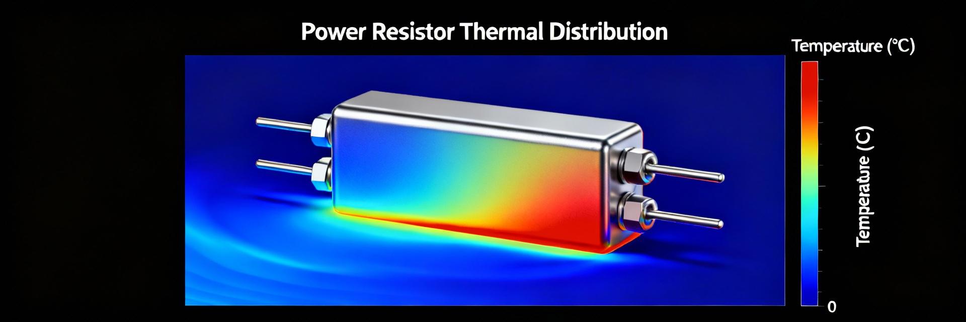
What the WDBR3-50RKLW family is designed for
Point: This resistor family is designed primarily for high-energy dissipation use: dynamic braking, snubber/inrush suppression, load-dump absorbers, and current limiting.
Evidence: Datasheet tables typically show nominal resistance and tolerance that map directly to these use cases.
Explanation: A low-profile, heatsink-mount construction allows mounting close to system heatsinks for effective steady-state dissipation, making the family suitable where board-mounted parts cannot absorb sustained energy safely.
How form factor and mounting affect performance
Point: Single-fixing heatsink mounting and mechanical footprint drive the thermal path and electrical isolation performance.
Evidence: Datasheet mounting notes and recommended torque values govern contact thermal resistance and creepage.
Explanation: Confirm heatsink flatness, mounting torque, and required insulation/clearance before ordering; inadequate interface or wrong creepage can reduce allowable continuous power or create safety failures in high-voltage systems.
Datasheet at a Glance: WDBR3-50RKLW Key Electrical Specs
Ohms, tolerance, and temperature coefficient
Point: These define circuit accuracy and sharing behavior under temperature change. Evidence: The specs table shows nominal ohms, ±% tolerance options, and ppm/°C tempco. Explanation: For braking resistors, choose a value that yields desired dissipated energy with headroom; tighter tolerance improves predictability, while a low tempco reduces drift during long dissipations.
Rated power, derating curves & continuous vs. peak ratings
Thermal, Pulse & Reliability Ratings: WDBR3-50RKLW Deep Dive
Thermal resistance and heatsink interface parameters
Tjunction = Tambient + Pdiss × (Rθ_heatsink + Rθ_interface + Rθ_part)
Explanation: Compute junction temperature using the sum of all thermal resistances; select thermal interface material (TIM) and torque to minimize interface resistance, and verify with on-board thermocouple measurements during validation.
Pulse, surge and short-duration ratings
Point: Pulse tables define the safe transient envelope. Evidence: Datasheet pulse rows list duration, repetition, and test conditions. Explanation: Translate motor energy (E = 0.5·C·V²) into equivalent pulse power over the event duration, then compare to the datasheet entry to confirm safety.
Real-World Application Example: Case Study
Sizing the WDBR3-50RKLW for Dynamic Braking
Scenario: A motor delivers 2,000 J over 2 seconds.
*Illustrative example: Always use measured system peak voltage for calculations.
Common pitfalls and mitigations
- ✘ Under-specifying heatsinks or ignoring pulse repetition intervals.
- ✔ Mitigate by adding thermal pads, forced-air cooling, and applying 20–50% headroom.
Selection & Validation Checklist
Pre-purchase Checklist
- Verify Resistance & Tolerance
- Check Steady-state Power vs Heatsink
- Confirm Mounting Hole & Torque
- Target 20-50% Safety Headroom
On-bench Validation
- Thermal Mapping (IR/Thermocouple)
- Repeated Pulse Load Testing
- Post-test Resistance Inspection
- Validate Creepage/Clearance
Summary: WDBR3-50RKLW Best Practices
- Confirm electrical fit: Extract nominal resistance, tolerance, and tempco so the WDBR3-50RKLW meets your target.
- Verify thermal adequacy: Use published Rθ values and derating curves to compute junction temperature; ensure mounting torque is correct.
- Respect pulse envelopes: Compare transient energy to pulse tables; if duty cycle is high, increase cooling or rating.
Common Questions and Answers
How do I find the nominal resistance for WDBR3-50RKLW on the datasheet? +
Point: The datasheet lists nominal resistance in the electrical characteristics table along with tolerance and tempco. Evidence: Look under the “Resistance” row. Explanation: Use that nominal value for initial circuit calculations, then adjust for tolerance and temperature-induced drift.
What pulse ratings for WDBR3-50RKLW should I compare to my transient? +
Point: Compare your transient duration and repetition to the datasheet pulse table entries. Evidence: Datasheets specify energy or peak power for fixed durations. Explanation: Convert your energy transient into the same units and duration to ensure the part matches or exceeds it.
What test steps validate WDBR3-50RKLW selection before deployment? +
Point: Perform steady-state dissipation, repeated pulse testing, and temperature mapping. Evidence: Successful validation shows stable resistance and acceptable temperature margins. Explanation: Include post-test resistance checks, fusing, and thermal monitoring in the final system.