XH5B-1215-5N Datasheet Deep Dive: Key Specs & Benchmarks
Key Takeaways (GEO Summary)
- Space Efficiency: 1.27mm pitch reduces PCB footprint by ~50% compared to standard 2.54mm connectors.
- High Precision: Dual-row 12-position SMT design with positioning bosses ensures ±0.03mm placement accuracy.
- Power Density: Handles 1A per contact, ideal for mezzanine board-to-board power and signal delivery.
- Reliability: Optimized for SAC305 reflow profiles with high-grade insulation (100 VAC rating).
Strategic Insight: Across connector benchmarks, half-pitch SMT connectors with a 1.27 mm pitch balance density and current handling. This deep dive parses the XH5B-1215-5N datasheet so PCB designers can rapidly assess mechanical clearance, electrical derating, and qualification steps for board-level use.
Connector Overview: XH5B-1215-5N Key Characteristics
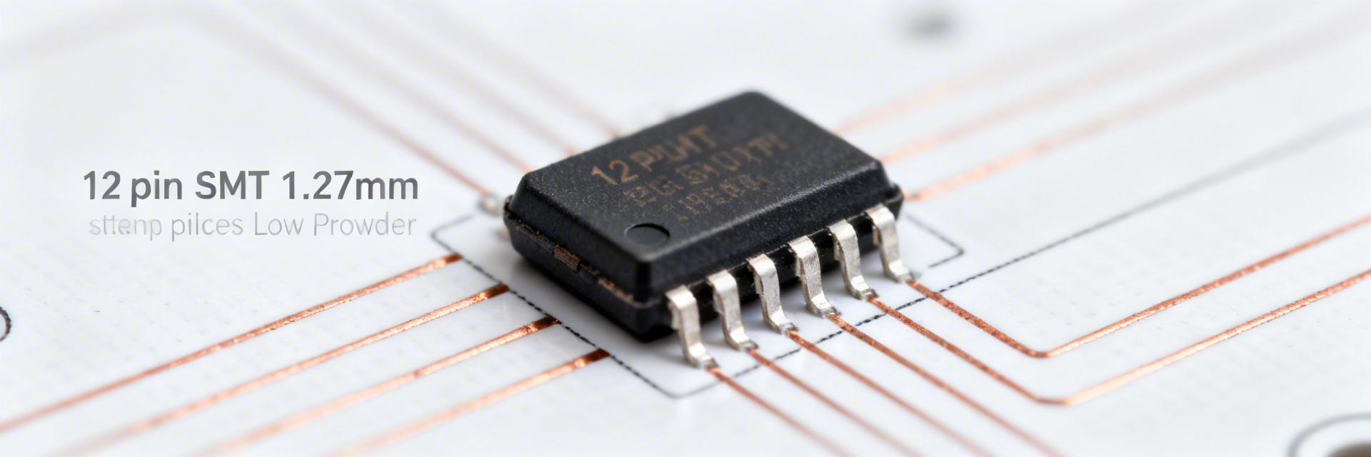
1. Physical Form Factor & User Benefits
The XH5B-1215-5N is a 1.27 mm half-pitch SMT rectangular connector with 12 positions. Unlike bulky 2.54mm headers, this low-profile vertical orientation allows for ultra-thin mezzanine stacks.
- Benefit: Saves significant Z-axis height in mobile and modular industrial devices.
- Mounting: Integrated bosses prevent misalignment during high-speed SMT placement.
2. Electrical Ratings & Reliability
Rated at 1A per contact and 100 VAC, the XH5B-1215-5N uses high-quality plating to minimize contact resistance.
Pro Tip: Apply a 70–80% derating rule (e.g., 0.7A continuous) for dense arrays to manage localized thermal rise.
Industry Benchmarks: XH5B-1215-5N vs. Alternatives
| Feature | XH5B-1215-5N | Standard 2.54mm Pitch | High-Density 0.5mm SMT |
|---|---|---|---|
| Pitch Density | 1.27 mm (Optimal) | 2.54 mm (Low) | 0.50 mm (Extreme) |
| Current per Pin | ~1.0 A | 3.0 A | ~0.3 A |
| PCB Real Estate | Balanced / Medium | Large | Minimal |
| Assembly Ease | High (Standard SMT) | Very High (Hand Solder) | Moderate (Requires AOI) |
"When integrating the XH5B-1215-5N, I often see designers overlook the positioning boss hole tolerances. While the pitch is 1.27mm, your drill hit tolerance for the bosses must be within ±0.03mm. If your PCB fab has high tolerance drift, the connector will 'float' during reflow, leading to cold joints on the end pins. I recommend using Non-Solder Mask Defined (NSMD) pads for this specific footprint to allow the solder to wrap around the pad edges for better mechanical shear strength."
Typical Application: Mezzanine Interconnect
Hand-drawn schematic, not a precise circuit diagram
Mezzanine Stack Design Tips:
- Mating Height: Always verify the combined stack height in the datasheet before selecting enclosure standoffs.
- EMI Shielding: For signals >100MHz, route ground vias between signal pairs to compensate for the lack of integrated shielding in 1.27mm connectors.
- Thermal Path: Avoid placing high-heat components directly under the connector keep-out zone.
Design & Procurement Checklist
- Match land pattern to datasheet Fig. 2.
- Verify pick-and-place nozzle clearance.
- Add fiducials within 10mm of footprint.
- Set Peak Temp to 260°C (SAC305).
- Inspect joints via X-Ray if using blind vias.
- Avoid backside reflow unless supported.
Common Questions
Q: What are the critical footprint specs for XH5B-1215-5N?
A: The pad pitch (1.27mm) and the positioning boss diameter are paramount. Ensure your solder mask expansion is set to 0.05mm to prevent bridging while maintaining maximum copper area.
Q: How should electrical derating be applied in dense arrays?
A: In clusters of 10+ connectors, derate the current to 0.7A per contact. Use 2oz copper pours for ground planes to act as a heatsink through the SMT pads.